Magnetic levitation devices are mainly divided into two kinds: power drive, and without power drive.
Power drive is divided into up-suction magnetic levitation and down-push magnetic levitation
This article mainly introduces the down-push magnetic levitation
Down-push magnetic levitation

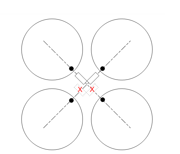
First of all, to introduce the principle, in fact, is very simple, is the magnetic control of the levitated object, the basic principle is Hall sensor in the levitated object directly below, when the detection of the levitated object to the left, the two sides of the coil a suction a pull, to push it to the right; Conversely, if the levitated object want to right movement, then the current of the two coils are reversed, a total of two groups of four such coils, you can limit the levitated object in the two-dimensional plane. However, the force generated by the coils is relatively small, so it can only push the levitated object to move in the horizontal plane, to overcome the gravity of the float to let it levitate, we need to add a large ring magnet under the four coils to provide repulsive force.
The materials of main things used in this device are a Hall sensor, Coil, large magnets, main control circuit board, and adaptor.
- Hall sensor: This is a component to measure the strength of the magnetic field, which can be converted into different voltage values through its vertical surface of the magnetic line of force strength so that we can get information on the position of the suspended object after reading with a microcontroller ADC. Hall sensor installation position is very delicate, it is measuring the magnetic force line through its vertical surface, that is, the magnetic force line issued by the suspended object, and we electromagnetic coil in the adjustment of the magnetic force line is also changing, if this change is Hall sensed the results are very unreliable, so the Hall installation position should be located in the middle height of the four coils, where the magnetic force line is just parallel to the Hall, no impact.

With a total of four coils in the front and back, and two Hall sensors to cooperate, you can levitate the suspended material stable.
In order to make the levitation more stable, we used the balance algorithm of PID control, understanding the PID algorithm helps us to understand the whole experimental principle, borrowing a paragraph from the introduction of PID online: in engineering practice, PID control is the most widely used regulator control mechanism. PID control, i.e., proportion; I represents the integral, i.e., integral; D represents the differential, i.e., differential; therefore, PID control, i.e., proportional-integral-differential control. integral; D represents differential, that is, differential; therefore, PID control, that is, proportional – integral – differential control. When the structure and parameters of the controlled object can not be fully grasped, or do not get an accurate mathematical model, other control methods are difficult to use, then the structure and parameters of the controller must be combined with experience and field debugging to decide, in this case, the most convenient to use PID regulation. First, proportional control is one of the simplest control methods, just like the proportionality coefficient in Hooke’s formula, when the output of the controller is proportional to the input signal, then a proportionality coefficient can be obtained. Secondly, integral control means that the output of the controller is related to the integral of the input error signal. Just as with an inductive element in a circuit, the voltage at a given moment is related to the integral of the current. Similarly, sometimes the output of the signal must be integrated with the input of the previous signal, and this integration is often a summation relationship, so using integral control is simple and easy. Finally, differential control means that the output of the controller is related to the differential of the input signal. The simplest differential relationship is that the velocity is a differential of the bit vector. When we control the equilibrium of the suspension, it is not enough to know the displacement of the suspension from the equilibrium position and thus use proportional control, for the same deviation from the displacement, the suspension may have a different speed, then we are required to have a different treatment of the suspension, and it happens that the speed is the differential of the bit vector, so we can achieve accurate real-time control of the suspension by differentiating the displacement input data. It can be seen that the PID controller is a kind of that dynamic control mechanism. The above is the basic principle of realizing the push-down magnetic levitation, with the help of the above basic principle, combined with certain software algorithm implementation, we can control the levitation dynamically.
If you don’t understand, you can ignore the nonsense… In short, we put the Hall element degree, that is, the position of the suspended object as an input variable into the PID function set a target value, that is, the reading value of the suspended object in the middle of the position, and then assign the output to the PWM drive coil, the rest is to adjust the PID parameters to let it control the levitation product.
2. Circuit: This is actually not a complex circuit, here send a simplified line diagram.

This is the way L298N and the coil connection, Hall sensor with analogRead read, PID has Arduino related library. Hall components generally need amplification circuit amplification, built-in amplification directly to the Arduino can be used, note that it must be linear! There is also a switch type that can only output 0 and 1 two values, we need the output analog voltage module.
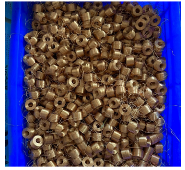
3. Coil, you can request the supplier to customize or purchase back copper wire according to the weight of the suspension, or the factory can process it by itself. The picture below is the factory-processed coil.

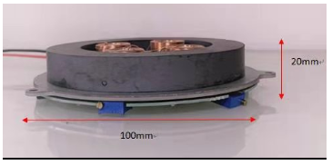
4. Large magnets, this is the picture after the addition of large magnets.

5. Adaptor: Generally use a 12v2A power adaptor, depending on the lightness of the levitation product, the maximum possible to use is 12v4A.

